Make costs visible
Assign consumption unambiguously to machines, installations, tenants or parts of a building – instead of estimating it with an allocation key.
Developed & produced in Switzerland
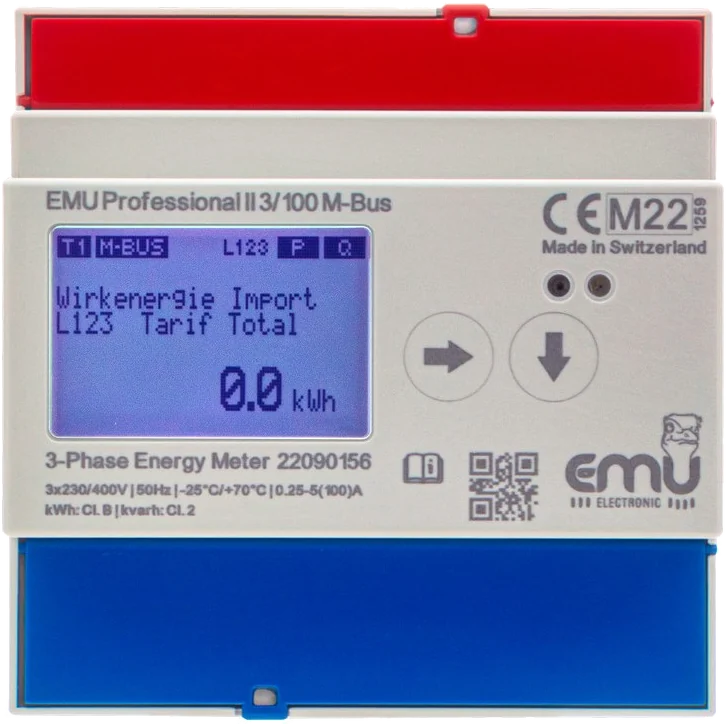
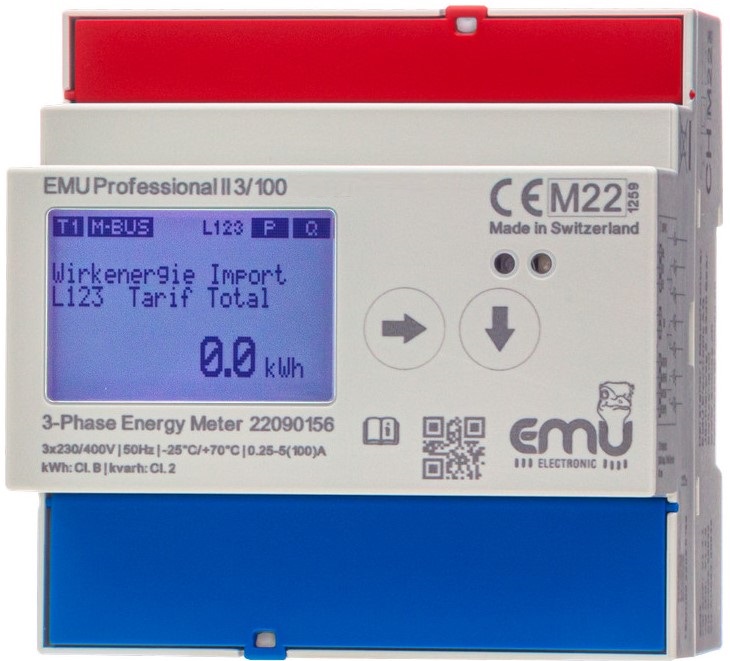
The Professional II measures three-phase – directly up to 100 A or via current transformers – and stores the load profile in the device. Its values are MID-compliant and therefore approved for internal and external billing. The meter mounts on a standard DIN rail.

Certifications
A meter meant for billing has to do more than measure. The Professional II carries the approvals required in Switzerland and in the EU for billing, third-party quantity allocation and energy management.
100,000
measured values in the load profile memory
3 years
of history in the device
4
tariffs for consumption and delivery
| MID B+D | Approved for billing in the EU |
|---|---|
| PTB-A 20.1 | Compliant with German verification law |
| PTB-A 50.7 | Third-party quantity allocation and energy management |
| ISO 50001 | Suitable for energy management systems |
| CLC/TR 50579 | Accurate with photovoltaics too |
Interfaces
The Professional II comes in versions with different interfaces. The choice matters: it determines the wiring, the network planning and the reading cycle – and which systems can later access the same values. That is why each interface has its own page, covering the principle behind it, how to size it and how it typically works with the EMU M-Center.
A rule of thumb to start with: M-Bus when many meters for different media come together in one building. RS-485 when the control system and automation already speak Modbus. TCP/IP when Ethernet is in place and the data is headed for the cloud or a dashboard. LoRa when there is no way to run a cable.
M-BusTwo wires, polarity-independent, up to 250 meters on the M-Center RS-485 / Modbus RTUFieldbus for control systems, register access TCP/IPModbus TCP and MQTT directly on the network LoRaRadio in the EU868 band, TTN template included KNXFrom Q1 2027
The interface is often chosen based on what the electrician knows, not on where the data needs to go later. If billing or a dashboard is added two years down the line, the decision is already locked in. That is why we would rather settle the target system than the terminal assignment at the start of a project.
Versions
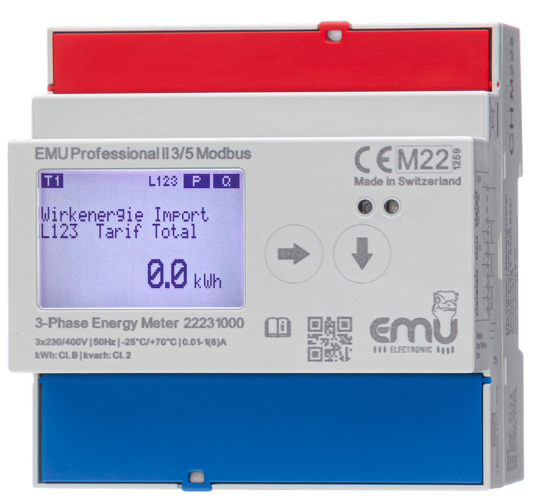
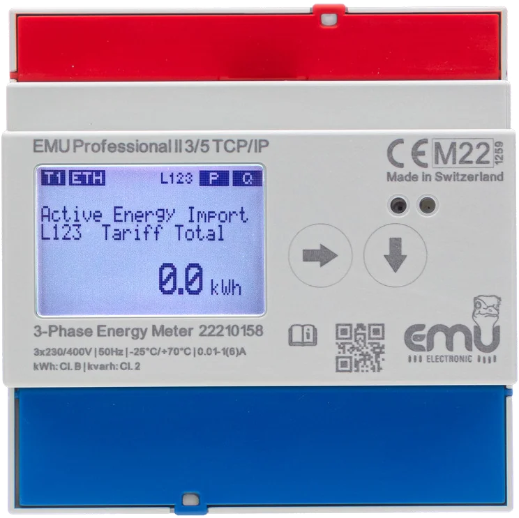
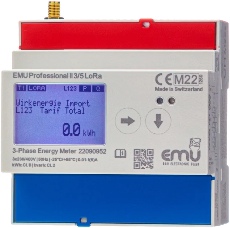
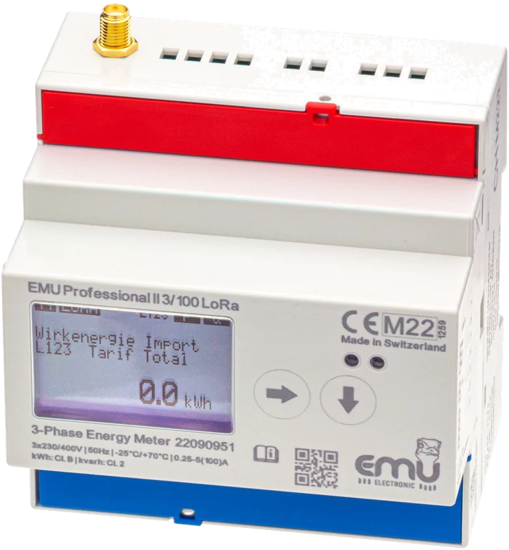
Two decisions determine the version: does the current flow directly through the meter or via transformers, and which interface do the values use to leave the device? The designation on the front panel records both.
Measuring range 0.25–5(100) A · −25 to +70 °C · class B for active energy, class 2 for reactive energy
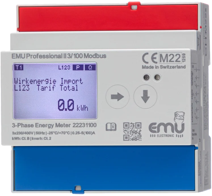
RS-485 explained
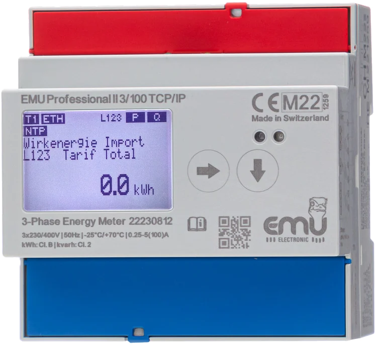
Direct connection 100 A
Web server, Modbus TCP, MQTT and NTP in the device.
TCP/IP explained
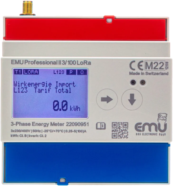
Direct connection 100 A
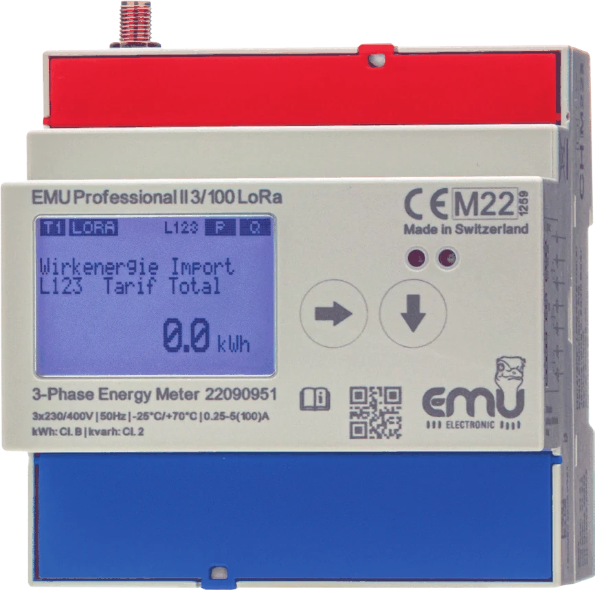
LoRaWAN 1.0.3 in the 863–870 MHz band. With internal antenna, or additionally with an SMA connector for an external antenna.
LoRa explained
Measuring range 0.01–1(6) A secondary · temperature range depending on version, see the print on the front panel · matching current transformers
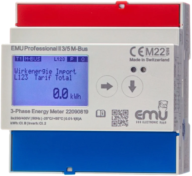
Current transformers /5 and /1 A
Transformer ratio can be reconfigured.
2×2 M-Bus terminals
M-Bus explained
Current transformers /5 and /1 A
Transformer ratio can be reconfigured.
Modbus RTU over RS485
RS-485 explained
Current transformers /5 and /1 A
Transformer ratio can be reconfigured.
Web server, Modbus TCP, MQTT and NTP in the device.
TCP/IP explained
Current transformers /5 and /1 A
Transformer ratio can be reconfigured.
With internal LoRa antenna, or additionally with an SMA connector for an external antenna.
LoRa explained
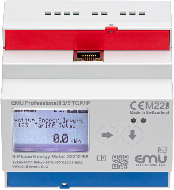
| Version | Interface | Article number |
|---|---|---|
| EMU Professional II 3/100 – direct connection up to 100 A | no interface | P20A0000 |
| EMU Professional II 3/100 M-Bus – direct connection up to 100 A | M-Bus | P20A000M |
| EMU Professional II 3/100 RS485 – direct connection up to 100 A | Modbus RTU (RS-485) | P20A000MO |
| EMU Professional II 3/100 TCP/IP – direct connection up to 100 A | TCP/IP | P20A000T |
| EMU Professional II 3/100 LoRa – direct connection up to 100 A | LoRa, internal antenna | P20A000LO |
| EMU Professional II 3/100 LoRa ext. antenna – direct connection up to 100 A | LoRa, internal antenna and SMA connector for external antenna | P20A000LE |
| EMU Professional II 3/100 KNX – direct connection up to 100 A | KNX (from Q1 2027) | P20A000K |
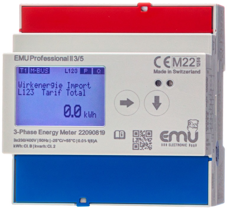
| EMU Professional II 3/5 – transformer connection | no interface | P21A0000 |
| EMU Professional II 3/5 M-Bus – transformer connection | M-Bus | P21A000M |
| EMU Professional II 3/5 RS485 – transformer connection | Modbus RTU (RS-485) | P21A000MO |
| EMU Professional II 3/5 TCP/IP – transformer connection | TCP/IP | P21A000T |
| EMU Professional II 3/5 LoRa – transformer connection | LoRa, internal antenna | P21A000LO |
| EMU Professional II 3/5 LoRa ext. antenna – transformer connection | LoRa, internal antenna and SMA connector for external antenna | P21A000LE |
| EMU Professional II 3/5 KNX – transformer connection | KNX (from Q1 2027) | P21A000K |
The photos show sample devices. The part number and data sheet are definitive for your order – data sheet and manuals are available for download further down.
Benefits
Assign consumption unambiguously to machines, installations, tenants or parts of a building – instead of estimating it with an allocation key.
The load profile shows when the peaks occur and where demand charges can be cut – stored in the device, even without a control system.
Continuously recorded, traceable readings as the basis for energy management to ISO 50001.
MID-compliant data for internal and external billing, including third-party quantity allocation.
Up to four tariffs for consumption and delivery – including for self-consumption associations and tenant electricity.
The TCP/IP version sends its values via MQTT to dashboards and cloud services.
Load profile memory
Most meters show a meter reading. That answers “how much”, but never “when”. Yet demand charges depend on exactly that: two businesses with the same annual consumption can pay very different amounts, depending on whether their consumption is spread evenly or concentrated in a few quarter-hours.
That is why the Professional II stores over 100,000 measured values internally – up to three years of history. The key point: even without a control system. The meter does not depend on anyone polling it regularly. If reading fails for two weeks – network changes, a faulty gateway, holidays – no values are lost; they are simply read out at the next opportunity.
This also changes how a project can be sequenced. You can install meters and start measuring before any energy management system exists. When Joulio-Web or a control system is added later, a year of history is already there instead of starting from zero.
Up to four tariffs for consumption and delivery separate peak and off-peak rates as well as energy fed in and energy drawn. In self-consumption associations and tenant electricity schemes, this is what ensures each party is billed for exactly what it drew or delivered.
In the event of a complaint, the disputed period can be reconstructed afterwards instead of estimated. That is the difference between a discussion and an analysis.
Areas of use
Consumption per machine or line, as a basis for efficiency projects and ISO 50001 / ISO 14001.
Consumption per rental unit or part of a building.
Billable measurement at charging points.
Accurate to CLC/TR 50579, with tariffs for consumption and delivery.
Clean allocation in self-consumption associations (ZEV) and tenant electricity schemes.
Submetering in existing buildings, including mixed meter estates.
Documents
Data sheet, quickstart and manual
PDF Data sheet1441 · English PDF Quickstart1450 · German / English PDF Manual1451 · English
One manual per version
PDF M-Bus interface1480 · English PDF TCP/IP interface1475 · English PDF Modbus registers1485 · English PDF LoRa interface1490 · English ZIP TCP/IP update toolFirmware update for the TCP/IP version
Decoder, payload tools and TTN template
GIT LoRa decoderRepository emuag/professional_II_lora GIT Payload generatorSource on GitHub WEB Payload decoderRuns in the browser WEB Payload generatorRuns in the browser
Frequently asked questions
Direct connection or transformers, verification period, tenant electricity, ZEV and LEG, interfaces: the answers are based on the meter’s data sheet and manuals and on current Swiss legislation.
Approval, accuracy and verification Direct connection Transformer connection Installation, housing and environment Load profile and data storage Interfaces Tenant electricity, ZEV and LEG
The EMU Professional II is a three-phase power meter for the 35 mm DIN rail. It measures active and reactive energy in both directions, stores the load profile in the device, handles up to four tariffs and outputs the values over M-Bus, Modbus RTU, TCP/IP or LoRa depending on the version. It is also referred to as a three-phase energy meter, kWh meter or DIN rail meter.
Class B to EN 50470-3 for active energy, which corresponds to a deviation of one percent. Class 2 to EN 62053 applies to the other measured quantities, that is two percent. Both classes apply across the whole measuring range and not only at the nominal point.
Yes. The meter is approved under MID module B+D, compliant with verification law to PTB-A 20.1, and in the load profile versions additionally certified to PTB-A 50.7 for third-party quantity allocation and energy management.
Under Article 6 of the FDJP Ordinance on Measuring Instruments for Electrical Energy and Power (EMmV, SR 941.251), electronic active energy meters must be re-verified every ten years by an authorised verification body. Meters with an electromechanical measuring element have a period of fifteen years.
Yes. For directly measuring active energy meters without upstream transformers, Article 6 paragraph 2 EMmV permits a statistical sampling procedure under Annex 4. If a lot passes the sample, all meters in the lot keep their verification validity for a further five years.
Responsibility lies with the person using the measuring instrument, which usually means the owner or operator of the installation. This also applies to sub-meters in a self-consumption association, not only to the distribution grid operator’s meters.
Yes. The Professional II meets CLC/FprTR 50579 and measures correctly even with harmonics in the 2 to 150 kilohertz range of the kind inverters produce. It counts consumption and delivery separately, which is required for self-consumption installations.
In Switzerland. Development, PCB assembly, final assembly and testing all take place here, and technical support comes from Baar in the canton of Zug.
With a direct connection the entire load current flows through the meter. No current transformers and no conversion are needed. That simplifies installation but limits the measurable current to what the device’s terminals can take.
The 3/100 direct connection variant measures up to 100 amperes per phase. Above that a transformer connection is required. For installations close to 100 amperes the transformer connection is the more robust choice.
On the direct connection, 1.5 to 35 square millimetres. The tightening torque is 2 newton metres, 3 newton metres maximum. Too little torque leads to contact resistance and heating at the terminal.
The starting current of the direct connection variant is 20 milliamperes. The meter does not record smaller currents. For standby measurements of individual devices that is the lower limit.
400 volts AC between the line conductors with a tolerance of plus/minus 20 percent, corresponding to 230 volts against neutral. Nominal frequency 50 hertz, 60 hertz on request. The measuring range runs from 40 to 65 hertz.
As soon as the expected continuous current exceeds 100 amperes, or the supply line has a cross-section above 35 square millimetres. Cramped space in the distribution board also argues for transformers, because then only thin measuring leads run to the meter.
With a transformer connection, current transformers measure the load current and map it to a small secondary current of 5 or 1 ampere. Only that secondary current runs through the meter. This allows installations up into the kiloampere range to be measured.
On the 5 ampere secondary variant, from 5/5 to 20,000/5 in steps of 5 amperes. On the 1 ampere secondary variant, from 1/1 to 4,000/1. The ratio is set in the meter, which then scales the values to the primary side.
The 3/5 variant tolerates up to 6 amperes of secondary current continuously. The starting current is 1 milliampere, so the meter also records very small loads relative to the transformer size.
1 to 6 square millimetres conductor cross-section, tightening torque 0.8 newton metres, 1 newton metre maximum. The current transformer circuits must never be open during operation, because dangerously high voltages arise otherwise.
Yes. Without the ratio correctly set, the meter scales the secondary values up incorrectly and the billing is wrong. The setting is described in the Professional II quickstart and should be recorded at commissioning.
Under Article 13 paragraph 1 EMmV the validity of verification of inductive and capacitive instrument transformers is unlimited. For other transformer types the Federal Office may set a re-verification period case by case at type approval.
Overall accuracy results from meter and transformer together. The meter meets class B to EN 50470-3. For that to hold in practice, the transformer class has to match and the burden has to stay within the transformer’s specification.
90 by 91 by 72 millimetres, which is 5 modules on the 35 mm DIN rail. The weight is around 350 grams.
The housing meets IP51, the terminals IP20. The meter is built to protection class II. For outdoor use or damp surroundings an appropriate enclosure is needed.
The range starts at minus 25 degrees Celsius; the upper limit depends on the version and is printed on the front panel – on the 3/100 direct connection variants it is plus 70 degrees, on several 3/5 transformer variants plus 55 degrees. The mechanical environment class is M2, the electromagnetic one E2.
Two or four tariffs depending on the version. Switching is done through control inputs with 230 volts AC. Consumption and delivery are counted separately, so feed-in tariffs can be covered as well.
The load profile memory records consumption at fixed intervals, on the Professional II every 15 minutes. From that, load peaks, standby consumption and operating times can be identified. For demand tariffs and for energy management to ISO 50001 this is the data basis.
Over 100,000 measured values, which corresponds to more than three years of history at 15-minute values. The meter records regardless of whether a control system is connected.
The internal clock keeps running on its buffer for 18 days. The measured values are held in EEPROM and remain there for at least ten years. When power returns, the meter resumes counting and the stored data is untouched.
Because only time-resolved values show which quantity was passed on to third parties at which point in time. The load profile versions of the Professional II are certified to PTB-A 50.7 for this.
Depending on version, M-Bus, Modbus RTU over RS-485, TCP/IP or LoRa. In addition there is an S0 pulse output and an optical interface. Each version has its own interface manual.
1.5 milliamperes, which is exactly one M-Bus unit load. Primary addresses can be set from 0 to 250, and the secondary address has eight digits. Factory settings are primary address 000, 2400 baud and the serial number as the secondary address.
300 to 9600 baud. In larger installations 2400 baud has proven itself, because range falls off considerably at higher baud rates. The EMU M-Center reads the meters at that setting.
The meter takes one eighth of a unit load on the RS-485 segment and works at 9600 to 115,200 baud. The register assignment is in the Modbus interface manual.
It has an RJ45 port with 100 Mbit/s full duplex and comes with a web server, Modbus TCP, an HTTP GET interface and NTP time synchronisation. By default it obtains its IP address via DHCP. MQTT allows direct connection to dashboards and cloud services.
863 to 870 megahertz, LoRaWAN 1.0.3, class C by default, class A is possible. Joining is by OTAA or ABP.
Yes. In The Things Network the EMU Professional II LoRa is available as a template. For other systems EMU provides the decoder on GitHub, together with a payload generator and a payload decoder as web tools.
The output conforms to EN 62053-31 and is built as an opto-MOSFET for 5 to 60 volts DC or AC. 1, 10, 100, 1000 or 10,000 pulses per kilowatt hour and pulse lengths of 2, 10, 30, 40 or 120 milliseconds can be set.
Yes, an infrared interface to D0 in accordance with EN 62056-21. It is used for on-site reading, independently of the bus wiring.
The M-Center reads the meter over M-Bus or Modbus RTU, stores the values and passes them on through MQTT, BACnet IP, OPC UA, Modbus TCP, API, FTP or email. The M-Center’s load profile function requires the EMU Professional II.
The distribution grid operator measures at the building’s connection point. Allocation to the individual tenants runs through sub-meters that the owner procures and operates. These meters have to meet the requirements of measuring instrument law, because their values are used for billing.
Several end consumers at the same location join together and appear to the grid operator as a single end consumer. The legal basis is Articles 17 and 18 of the Energy Act, in the version in force since 1 January 2025. Under Article 17 paragraph 2 EnG, tenants and lessees can be included.
In a virtual association the distribution grid operator’s measurements remain in place and are combined arithmetically, instead of running physically through a shared connection point. The term comes from grid operator practice; the Energy Act itself does not use it. Which variant is possible is determined by the responsible distribution grid operator.
An LEG under Article 17d of the Electricity Supply Act, in force since 1 January 2026, connects end consumers, producers of renewable electricity and storage operators within the same grid area, on the same grid level and physically close to each other. Its extent covers at most the territory of one municipality.
Under Article 17d StromVG every participant must have a smart metering system, provided by the distribution grid operator. Billing towards the grid is based on these metering systems, not on private sub-meters.
It measures behind the connection point: individual flats and commercial units, charging points, heat pumps, photovoltaics and storage. These values are the basis for internal billing, for checking the allocation keys and for monitoring. Metering towards the grid remains the responsibility of the distribution grid operator.
A version with bidirectional measurement and load profile memory. That makes production, self-consumption and feed-in separately traceable, and up to four tariffs can be spread across consumption and delivery.
Yes. The ten-year re-verification period under Article 6 EMmV attaches to the measuring instrument, not to who operates it. If its values are used for billing, the meter has to hold valid verification.
Legal information from the Energy Act (EnG, SR 730.0) Art. 17 and 18, Electricity Supply Act (StromVG, SR 734.7) Art. 17d and 17e and the FDJP Ordinance on Measuring Instruments for Electrical Energy and Power (EMmV, SR 941.251) Art. 6 and 13. As at October 2026. The legal text in force at the time is definitive; this information does not replace legal advice.
Tell us where the data needs to go – control system, billing, cloud or all three. The interface follows from that.
Phone
+41 (0)41 545 03 00
Technical support
helpdesk@emuag.ch
Orders Switzerland
orders@emuag.ch