Split-core current transformers
TQ split-core current transformers: retrofitting without disconnecting
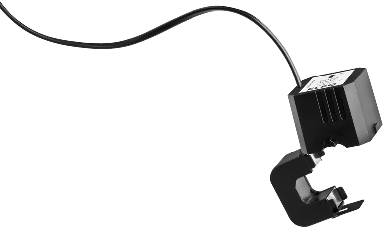
The core can be opened and placed around an existing insulated conductor. An audible click confirms it is closed. 1 A secondary current, 100 to 1000 A primary, 3 m permanently attached lead.
Principle
When is a split-core current transformer worth it?
In existing buildings, disconnecting a conductor is rarely an option: the installation is running, shutting down costs production or comfort, and sometimes nobody knows exactly what is connected to that outgoing circuit any more. That is precisely what split-core transformers are for. The core is opened, placed around the conductor and closed again.
What that costs
The parting line in the core means a small air gap. Split-core transformers of the same size therefore usually reach class 1 instead of class 0.5, and the permissible burden, at 0.2 VA, is considerably smaller. For monitoring, load profile recording and internal cost allocation that is enough; for billing that requires class 0.5, the choice is limited.
Typical uses
- A metering concept added later in an existing building
- Individual outgoing circuits that were not previously recorded
- Temporary measurements for analysis before a conversion
- Sub-distribution boards where no shutdown is possible
Type overview
Which split-core current transformers are available?
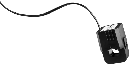
Two sizes: TQ40 for 100 to 400 A with openings of Ø 18 and Ø 28 mm, TQ50 for 500 to 1000 A with Ø 42 mm. All types deliver 1 A on the secondary side.
| Type | Primary current | Secondary | Class | Burden | Cable opening | Dimensions W × H × D |
|---|---|---|---|---|---|---|
| TQ40-B 100/1A | 100 A | 1 A | 1 | 0.2 VA | Ø 18 mm | 67 × 45 × 49 mm |
| TQ40-B 150/1A | 150 A | 1 A | 1 | 0.2 VA | Ø 18 mm | 67 × 45 × 49 mm |
| TQ40-C 200/1A | 200 A | 1 A | 1 | 0.2 VA | Ø 28 mm | 67 × 45 × 49 mm |
| TQ40-C 250/1A | 250 A | 1 A | 1 | 0.2 VA | Ø 28 mm | 67 × 45 × 49 mm |
| TQ40-C 300/1A | 300 A | 1 A | 1 | 0.2 VA | Ø 28 mm | 67 × 45 × 49 mm |
| TQ40-C 400/1A | 400 A | 1 A | 1 | 0.2 VA | Ø 28 mm | 66 × 44 × 48 mm |
| TQ50-E 500/1A | 500 A | 1 A | 1 | 0.2 VA | Ø 42 mm | 66 × 97 × 55 mm |
| TQ50-E 600/1A | 600 A | 1 A | 1 | 0.2 VA | Ø 42 mm | 66 × 97 × 55 mm |
| TQ50-E 800/1A | 800 A | 1 A | 1 | 0.2 VA | Ø 42 mm | 66 × 97 × 55 mm |
| TQ50-E 1000/1A | 1000 A | 1 A | 1 | 0.2 VA | Ø 42 mm | 66 × 97 × 55 mm |
| TQ50-L 500/1A | 500 A | 1 A | 0.5 | 0.5 VA | Ø 42 × 84 mm | 66 × 139 × 55 mm |
| TQ50-L 1000/1A | 1000 A | 1 A | 1 | 0.2 VA | 2 × Ø 42 mm | 66 × 139 × 55 mm |
Scope of delivery
Secondary lead 0.5 mm², 3 m, colour coded, permanently attached. Plus two UV-resistant cable ties for fixing. PVC housing.
Click and go
The catch engages audibly. That click is the test criterion: a core that is not fully closed reads considerably too low.
Insulated conductors only
The TQ series is expressly intended for insulated conductors. For bare conductors and busbars, solid-core transformers are used.
Sizing
How do I size a current transformer correctly?
A transformer is not chosen by the fuse rating but by the current that actually flows. A transformer chosen too large measures inaccurately in the lower load range; one chosen too small goes into saturation at load peaks.
Working range 5 to 120 percent
EMU recommends choosing the transformer so that the operating current lies between 5 % and 120 % of the rated current. Below 5 % the relative error rises sharply; above 120 % the core leaves its linear range.
—
In practice that means: the smallest regularly occurring load current should be above 5 %, the largest expected one below 120 %. Where both cannot hold at once, the range that is billed or analysed decides.
Worked example
An installation is fused at 250 A; the measured continuous current lies between 40 A and 180 A.
- 250/5 A: 5 % = 12.5 A, 120 % = 300 A. Both limits fit.
- 600/5 A: 5 % = 30 A. The lower load range falls partly below that – inaccurate.
- 150/5 A: 120 % = 180 A. The peak sits exactly on the limit – too tight.
250/5 A is chosen. The fuse rating alone would also have suggested 600/5 A – and would have been measurably wrong in the part-load range.
Accuracy class
The class of the transformer limits the overall accuracy of the measurement. A class B meter is of little use with a class 3 transformer in front of it. For billing and third-party quantity allocation, class 0.5 or better is usual.
Burden
The burden is the sum of meter impedance, terminals and conductor resistance, given in VA. As long as the actual burden stays well below the rated burden, the transformer keeps its class. Long measuring leads with a small cross-section drive this figure up.
Conductor cross-section
At 5 A secondary current the voltage drop grows with the square of the current and with the length. Short runs and at least 2.5 mm² are the rule; over greater distances either increase the cross-section or choose a transformer with a higher rated burden.
A peculiarity of 1 A secondary current
Losses on the measuring lead rise with the square of the current. At 1 A instead of 5 A they drop to one twenty-fifth. The small rated burden of 0.2 VA is therefore less restrictive in practice than the figure first suggests – provided the meter is designed for 1 A.
Safety
Why the secondary circuit of a current transformer must never be left open
A current transformer is a current source, not a voltage source. As long as the secondary circuit is closed, it drives the transformed current through the burden and the voltage stays small. If the circuit is opened while primary current is flowing, the transformer tries to keep driving the current: the core goes into saturation and dangerously high voltage peaks arise at terminals S1/S2. That can destroy the insulation, permanently damage the transformer and endanger people.
Hence the rule: before any work on the meter, the secondary circuit is short-circuited, not disconnected.
Plan shorting terminals in from the start
A test terminal block with shorting links belongs between transformer and meter. It costs little but is often left out – and is missing exactly when, years later, someone has to replace the meter. Without these terminals the only option left is to switch off the installation.
- One terminal per phase with isolating blade and shorting link
- Order: link first, then disconnect towards the meter
- Label the terminal block: which transformer, which phase, which ratio
- Test sockets allow a check measurement during operation
Order when replacing a meter
- Close the shorting links in the test terminal block
- Check that the links really make contact
- Only now disconnect the leads to the meter
- Connect the new meter, set the transformer ratio
- Open the links and check the measured values for plausibility against the load
Further points that go wrong in practice
The direction P1 → P2 has to match the direction of energy flow, otherwise the meter counts consumption as delivery. S1 and S2 must not be swapped. The transformer ratio must be set in the meter and documented in the circuit diagram – without it, billing cannot be traced later.
Frequently asked questions
Frequently asked questions about split-core current transformers
Fundamentals, technical data, installation and safety of the TQ series.
Fundamentals Technical data Installation Safety
Fundamentals
What is a split-core current transformer?
A transformer whose core can be opened. It is placed around an existing conductor and closed again, without the wiring having to be disconnected. The design is called split-core, colloquially also a clamp-on transformer.
When is a split-core transformer worth it?
Whenever measurements need to be added later: when extending an existing installation, when building a metering concept in an existing building, or for temporary measurements. The solid-core transformer remains the more robust and usually more accurate choice where new wiring is being done anyway.
What secondary current does the TQ series deliver?
All types in the TQ series work with 1 A secondary current, so a meter version for 1 A is required; in the /1 A variant the EMU Professional II covers ratios from 1/1 to 4,000/1.
Does the installation have to be switched off for fitting?
Opening and closing the core itself does not require the conductor to be disconnected. Whether work may be carried out live depends on the applicable working regulations and the qualification of the person doing it – that is an organisational question, not a product one.
Technical data
Which primary currents are available?
From 100 A on the TQ40-B to 1000 A on the TQ50-E and TQ50-L. Size TQ40 covers 100 to 400 A, size TQ50 the ranges from 500 to 1000 A.
Which cable openings are available?
Ø 18 mm on the TQ40-B, Ø 28 mm on the TQ40-C and Ø 42 mm on the TQ50 series. The TQ50-L offers an opening of 42 × 84 mm, or two openings of Ø 42 mm each.
What accuracy class do the split-core transformers reach?
Class 1 to IEC 60044-1 on most types, class 0.5 on the TQ50-L 500/1A. For billing that requires class 0.5, the choice is therefore limited.
How large is the burden?
A maximum of 0.2 VA at the cable end, 0.5 VA on the TQ50-L 500/1A. Because the secondary current is only 1 A, the influence of lead length on the burden is considerably smaller than with 5 A transformers.
How long is the secondary lead?
The transformers have a permanently attached lead 3 m long with a 0.5 mm² cross-section, colour coded. The housing is PVC.
Installation
How is a split-core transformer installed?
The core is opened, placed around the conductor and closed until an audible click confirms correct locking. Two UV-resistant cable ties for fixing are supplied. A core that is not fully closed distorts the measurement considerably.
May the transformers be placed around bare conductors?
No. The TQ series is expressly intended for insulated conductors only. For bare conductors or busbars, solid-core transformers with the corresponding insulation testing are used.
What do I have to watch for regarding direction?
As with every current transformer, P1 faces the supply, P2 the load. The marking is on the housing. With the wrong direction the sign of the measurement reverses.
Can I extend the secondary lead?
In principle yes, as long as the total burden stays below the rated value. At 1 A secondary current there is considerably more headroom than at 5 A. The extension has to be made safely and arranged so that the circuit cannot be opened unintentionally.
Safety
Does the short-circuit rule apply to split-core transformers too?
Yes, without exception. A transformer with 1 A secondary current also produces dangerous voltages at an open secondary circuit. Before any work the circuit is bridged by shorting terminals and not simply disconnected.
Do I need a test terminal block here as well?
Yes. The permanently attached lead sensibly ends in a test terminal block with shorting links, not directly at the meter. Only that way can the meter be replaced later without switching off the installation.
What happens if the core does not close cleanly?
An air gap in the core reduces the coupling, and the transformer reads considerably too low. The click when closing is therefore a test criterion, not a convenience feature. Dirty mating faces should be cleaned before fitting.
Technical data from the product pages of EMU Metering (Solid-core current transformers, split-core current transformers), as at October 2026. Legal information from the EMmV (SR 941.251). The data sheet and order confirmation are definitive for ordering.
Which transformer suits your installation?
Send us the rated current of the fuse, the conductor cross-section or busbar dimensions, the lead length to the meter and the accuracy required. We will calculate the burden and class.
Phone
+41 (0)41 545 03 00
Technical support
helpdesk@emuag.ch
Orders Switzerland
orders@emuag.ch