Solid-core current transformers
EMCT solid-core current transformers with 5 A secondary current
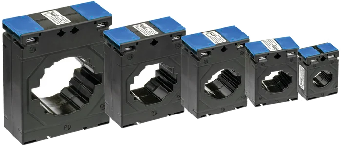
Closed core, six sizes, primary currents from 60 to 1250 A. For cables up to Ø 65 mm and busbars up to 80 × 10 mm – the usual choice when the installation is being newly wired anyway.
Principle
What is a solid-core current transformer?
The primary conductor is led through the window of a closed ring core and thereby forms the primary winding, usually with a single turn. The current creates a magnetic field that induces a proportionally smaller current in the secondary winding – on the EMCT series, 5 A at rated current.
Why the core is closed
A continuous core with no parting line carries the magnetic flux without an air gap. That is why solid-core transformers are more accurate than split-core ones of the same size. The price: for installation, the conductor has to be disconnected once, or the busbar slid in before it is bolted up.
Where they are used
- Main and sub-distribution boards in new buildings
- Outgoing circuits to production plant, charging infrastructure and heat pumps
- Measurements that are billed and require class 0.5
- Busbar systems where a split-core transformer does not fit
Type overview
Which solid-core current transformers are available?
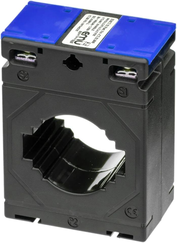
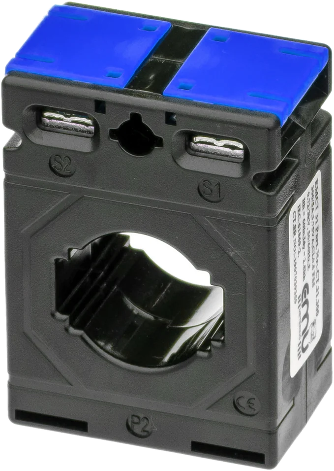
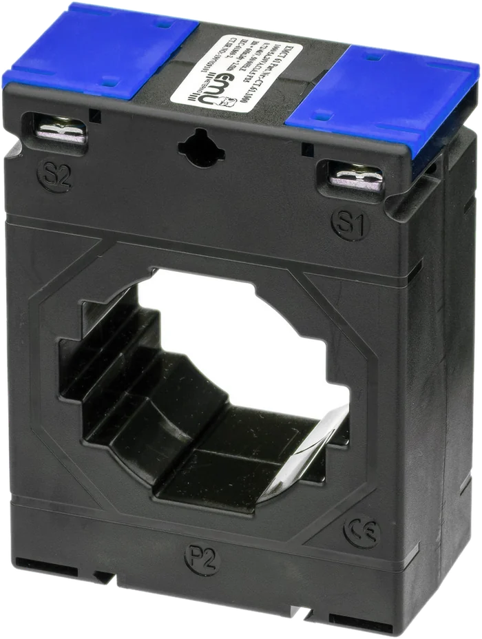
Six sizes from EMCT 21 to EMCT 81. Within one size, the rated burden changes with the primary current, and from 250 A upwards so does the accuracy class.
| Type | Primary current | Secondary | Rated burden | Class | Dimensions W × H × D | Part no. |
|---|---|---|---|---|---|---|
| EMCT 21 | 60 A | 5 A | 1.5 VA | 1 | 51 × 70 × 30 mm | CT.21.060 |
| EMCT 31 | 80 A | 5 A | 1.5 VA | 1 | 50 × 70 × 30 mm | CT.31.080 |
| EMCT 31 | 100 A | 5 A | 2.5 VA | 1 | 50 × 70 × 30 mm | CT.31.100 |
| EMCT 31 | 125 A | 5 A | 2.5 VA | 1 | 50 × 70 × 30 mm | CT.31.125 |
| EMCT 31 | 150 A | 5 A | 2.5 VA | 1 | 50 × 70 × 30 mm | CT.31.150 |
| EMCT 31 | 200 A | 5 A | 2.5 VA | 1 | 50 × 70 × 30 mm | CT.31.200 |
| EMCT 31 | 250 A | 5 A | 5 VA | 0.5 | 50 × 70 × 30 mm | CT.31.250 |
| EMCT 31 | 300 A | 5 A | 5 VA | 0.5 | 50 × 70 × 30 mm | CT.31.300 |
| EMCT 31 | 400 A | 5 A | 5 VA | 0.5 | 50 × 70 × 30 mm | CT.31.400 |
| EMCT 41 | 250 A | 5 A | 2.5 VA | 0.5 | 62 × 78 × 40 mm | CT.41.250 |
| EMCT 41 | 300 A | 5 A | 5 VA | 0.5 | 62 × 78 × 40 mm | CT.41.300 |
| EMCT 41 | 400 A | 5 A | 5 VA | 0.5 | 62 × 78 × 40 mm | CT.41.400 |
| EMCT 41 | 500 A | 5 A | 5 VA | 0.5 | 62 × 78 × 40 mm | CT.41.500 |
| EMCT 51 | 600 A | 5 A | 10 VA | 0.5 | 74 × 98 × 50 mm | CT.51.600 |
| EMCT 51 | 800 A | 5 A | 12.5 VA | 0.5 | 74 × 98 × 50 mm | CT.51.800 |
| EMCT 61 | 600 A | 5 A | 15 VA | 0.5 | 86 × 110 × 45 mm | CT.61.600 |
| EMCT 61 | 800 A | 5 A | 20 VA | 0.5 | 86 × 110 × 45 mm | CT.61.800 |
| EMCT 61 | 1000 A | 5 A | 20 VA | 0.5 | 86 × 110 × 45 mm | CT.61.1000 |
| EMCT 61 | 1200 A | 5 A | 20 VA | 0.5 | 86 × 110 × 45 mm | CT.61.1200 |
| EMCT 81 | 800 A | 5 A | 10 VA | 0.5 | 104 × 126 × 45 mm | CT.81.800 |
| EMCT 81 | 1250 A | 5 A | 20 VA | 0.5 | 104 × 126 × 45 mm | CT.81.1250 |
The rated burden depends on the type. Individual units carry a value on the rating plate that differs from the catalogue – check the figure against the data sheet of the specific type before sizing.
Cable openings
Ø 21, 26, 31, 41, 51 and 65 mm. What counts is the outside diameter of the cable including insulation, not the conductor cross-section.
Busbars
20 × 10, 30 × 10, 40 × 10, 50 × 10, 60 × 10 and 80 × 10 mm. With several parallel bars per phase, the whole stack counts.
DIN rail adapter
For EMCT 21, 31 and 41 a snap-on adapter for the DIN rail is available as an accessory, one per transformer. For EMCT 51, 61 and 81 none is listed.
Sizing
How do I size a current transformer correctly?
A transformer is not chosen by the fuse rating but by the current that actually flows. A transformer chosen too large measures inaccurately in the lower load range; one chosen too small goes into saturation at load peaks.
Working range 5 to 120 percent
EMU recommends choosing the transformer so that the operating current lies between 5 % and 120 % of the rated current. Below 5 % the relative error rises sharply; above 120 % the core leaves its linear range.
—
In practice that means: the smallest regularly occurring load current should be above 5 %, the largest expected one below 120 %. Where both cannot hold at once, the range that is billed or analysed decides.
Worked example
An installation is fused at 250 A; the measured continuous current lies between 40 A and 180 A.
- 250/5 A: 5 % = 12.5 A, 120 % = 300 A. Both limits fit.
- 600/5 A: 5 % = 30 A. The lower load range falls partly below that – inaccurate.
- 150/5 A: 120 % = 180 A. The peak sits exactly on the limit – too tight.
250/5 A is chosen. The fuse rating alone would also have suggested 600/5 A – and would have been measurably wrong in the part-load range.
Accuracy class
The class of the transformer limits the overall accuracy of the measurement. A class B meter is of little use with a class 3 transformer in front of it. For billing and third-party quantity allocation, class 0.5 or better is usual.
Burden
The burden is the sum of meter impedance, terminals and conductor resistance, given in VA. As long as the actual burden stays well below the rated burden, the transformer keeps its class. Long measuring leads with a small cross-section drive this figure up.
Conductor cross-section
At 5 A secondary current the voltage drop grows with the square of the current and with the length. Short runs and at least 2.5 mm² are the rule; over greater distances either increase the cross-section or choose a transformer with a higher rated burden.
Typical of the EMCT series
The rated burden rises with the primary current: 1.5 VA on the EMCT 21 up to 20 VA on the EMCT 61 and 81. Anyone with long measuring leads therefore chooses not only by current but also by burden – or puts the meter closer to the transformer.
Safety
Why the secondary circuit of a current transformer must never be left open
A current transformer is a current source, not a voltage source. As long as the secondary circuit is closed, it drives the transformed current through the burden and the voltage stays small. If the circuit is opened while primary current is flowing, the transformer tries to keep driving the current: the core goes into saturation and dangerously high voltage peaks arise at terminals S1/S2. That can destroy the insulation, permanently damage the transformer and endanger people.
Hence the rule: before any work on the meter, the secondary circuit is short-circuited, not disconnected.
Plan shorting terminals in from the start
A test terminal block with shorting links belongs between transformer and meter. It costs little but is often left out – and is missing exactly when, years later, someone has to replace the meter. Without these terminals the only option left is to switch off the installation.
- One terminal per phase with isolating blade and shorting link
- Order: link first, then disconnect towards the meter
- Label the terminal block: which transformer, which phase, which ratio
- Test sockets allow a check measurement during operation
Order when replacing a meter
- Close the shorting links in the test terminal block
- Check that the links really make contact
- Only now disconnect the leads to the meter
- Connect the new meter, set the transformer ratio
- Open the links and check the measured values for plausibility against the load
Further points that go wrong in practice
The direction P1 → P2 has to match the direction of energy flow, otherwise the meter counts consumption as delivery. S1 and S2 must not be swapped. The transformer ratio must be set in the meter and documented in the circuit diagram – without it, billing cannot be traced later.
Frequently asked questions
Frequently asked questions about solid-core current transformers
Selection, installation, connection and operation of the EMCT series.
Selection Installation Connection and safety Operation
Selection
Which size do I need?
The size follows from what has to fit through the window: cable diameter or busbar dimensions. The EMCT series covers cable openings from Ø 21 to Ø 65 mm and busbars from 20 × 10 to 80 × 10 mm. Only after that comes the question of primary current.
Which primary currents are available?
The EMCT series ranges from 60 A on the EMCT 21 to 1250 A on the EMCT 81. Within one size there are several primary currents; on the EMCT 31, for instance, 80, 100, 125, 150, 200, 250, 300 and 400 A.
What secondary current do the transformers deliver?
All types in the EMCT series work with 5 A secondary current. The matching version is the EMU Professional II 3/5, designed for 5 A secondary current and able to cover ratios from 5/5 to 20,000/5.
Which accuracy classes are available?
The smaller types up to 200 A are class 1, from 250 A upwards class 0.5. For billing and third-party quantity allocation, class 0.5 is the usual choice. Classification follows DIN EN 61869-2.
How high is the rated burden?
Depending on type, between 1.5 VA on the EMCT 21 and 20 VA on the EMCT 61 and EMCT 81. The full assignment is in the table on this page. The actual burden from meter, terminals and leads has to stay below it.
Installation
How is a solid-core transformer installed?
The conductor or busbar is led through the window, in the direction P1 to P2. The transformer is secured with the fixing material supplied. Because the ring is closed, the conductor has to be disconnected once, or the busbar slid in before installation.
Is DIN rail mounting available?
For types EMCT 21, 31 and 41 a snap-on adapter for the DIN rail is available as an accessory, one per transformer. For the larger types EMCT 51, 61 and 81 no adapter is listed; they are fixed directly.
How much space do I have to allow for?
Dimensions range from 51 × 70 × 30 mm on the EMCT 21 to 104 × 126 × 45 mm on the EMCT 81. On top of that comes space for the secondary terminals and the bending radius of the measuring leads. The exact dimensions are in the table.
Can I change the measuring range by passing the conductor through several times?
At small currents the conductor is occasionally passed through the window several times to multiply the ratio. Whether this is permitted for a particular transformer, and which class then applies, is stated in that type’s data sheet. For billing it should be avoided.
Connection and safety
May I disconnect the secondary circuit during operation?
No. With primary current flowing, dangerously high voltages arise at an open secondary circuit. Before any work the circuit is bridged by shorting terminals. Without such terminals the only option left is to switch off the installation.
Which terminals do I need between transformer and meter?
A test terminal block with isolating blades and shorting links, one terminal per phase. Test sockets additionally allow a check measurement during operation without undoing anything. The block belongs in the plan, not in the rework.
Which way round is the transformer fitted?
P1 faces the supply, P2 the load. The markings are embossed on the housing. If the transformer is fitted the wrong way round, the meter counts consumption as delivery – in self-consumption installations that only shows up in the billing.
What happens if the secondary terminals are swapped?
S1 and S2 swapped has the same effect as a transformer fitted the wrong way round: the sign of the affected phase reverses. In three-phase measurement this shows up as implausible power values on a single phase.
Operation
Do I have to set the transformer ratio in the meter?
Yes. Without the ratio correctly set, the meter scales the secondary values to the primary side incorrectly. The setting belongs in the commissioning record and in the circuit diagram, so that it does not have to be guessed again at the next meter replacement.
How do I check that the measurement is right?
Switch on a known load and compare the displayed current against a clamp measurement on the primary conductor. Deviations by a round factor almost always point to a wrongly set transformer ratio, not to a defective transformer.
Are current transformers subject to verification?
Under Article 13 paragraph 1 EMmV the validity of verification of inductive and capacitive instrument transformers is unlimited. For other transformer types the Federal Office may set a re-verification period at type approval. The meter itself is subject to its own period independently of that.
Which EMU meter goes with these transformers?
The EMU Professional II in the 3/5 version with 5 A secondary current. It accepts ratios from 5/5 to 20,000/5 in steps of 5 A and tolerates up to 6 A continuously on the secondary side.
Technical data from the product pages of EMU Metering (Solid-core current transformers, split-core current transformers), as at October 2026. Legal information from the EMmV (SR 941.251). The data sheet and order confirmation are definitive for ordering.
Which transformer suits your installation?
Send us the rated current of the fuse, the conductor cross-section or busbar dimensions, the lead length to the meter and the accuracy required. We will calculate the burden and class.
Phone
+41 (0)41 545 03 00
Technical support
helpdesk@emuag.ch
Orders Switzerland
orders@emuag.ch