Current transformers
Current transformers for power meters: selection, sizing and wiring
Above 100 A, the Professional II no longer measures directly. That is where current transformers come in: they map the load current to 5 A or 1 A. This page covers which design, which rated current and which class to choose – and why a test terminal block with shorting links belongs in every plan.
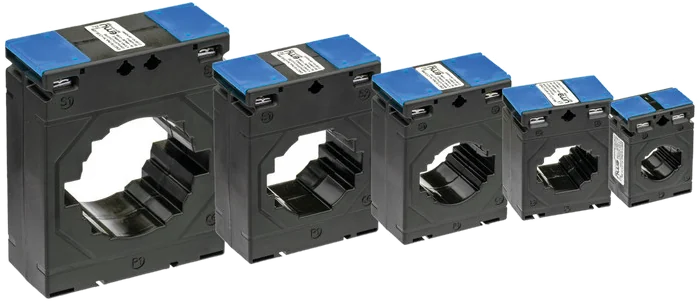
Two designs
Solid-core or split-core current transformer?
The decision almost always comes down to whether the conductor can be disconnected. Everything else – rated current, class, burden – applies equally to both designs.
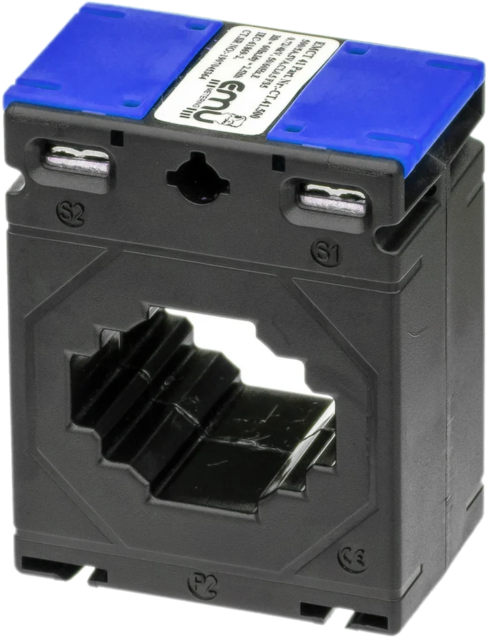
Closed core
EMCT solid-core current transformers
5 A secondary, 60 to 1250 A primary, class 1 or 0.5. For cables and busbars, where wiring is being done anyway while the installation is built.
To the solid-core transformers
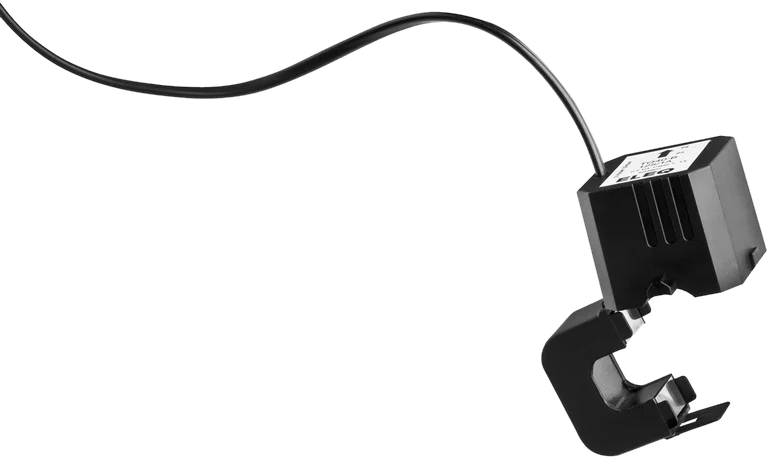
Split core
TQ split-core current transformers
1 A secondary, 100 to 1000 A primary, 3 m connecting lead. For retrofitting around existing, insulated conductors.
To the split-core transformers
| Feature | Solid-core EMCT | Split-core TQ |
|---|---|---|
| Secondary current | 5 A | 1 A |
| Primary current | 60 to 1250 A | 100 to 1000 A |
| Accuracy class | 1 to 0.5 | 1, on the TQ50-L 500 also 0.5 |
| Rated burden | 1.5 to 20 VA | 0.2 VA, on the TQ50-L 500 0.5 VA |
| Installation | Disconnect the conductor or slide in the busbar | Clamp around the existing conductor |
| Conductor | Cable and busbar | insulated conductors only |
| Connection | Terminals S1 and S2 | permanently attached lead, 3 m |
| Standard | DIN EN 61869-2 | IEC 60044-1 |
| Typical use | New build, main distribution, billing | Retrofit in existing buildings, monitoring |
Sizing
How do I size a current transformer correctly?
A transformer is not chosen by the fuse rating but by the current that actually flows. A transformer chosen too large measures inaccurately in the lower load range; one chosen too small goes into saturation at load peaks.
Working range 5 to 120 percent
EMU recommends choosing the transformer so that the operating current lies between 5 % and 120 % of the rated current. Below 5 % the relative error rises sharply; above 120 % the core leaves its linear range.
—
In practice that means: the smallest regularly occurring load current should be above 5 %, the largest expected one below 120 %. Where both cannot hold at once, the range that is billed or analysed decides.
Worked example
An installation is fused at 250 A; the measured continuous current lies between 40 A and 180 A.
- 250/5 A: 5 % = 12.5 A, 120 % = 300 A. Both limits fit.
- 600/5 A: 5 % = 30 A. The lower load range falls partly below that – inaccurate.
- 150/5 A: 120 % = 180 A. The peak sits exactly on the limit – too tight.
250/5 A is chosen. The fuse rating alone would also have suggested 600/5 A – and would have been measurably wrong in the part-load range.
Accuracy class
The class of the transformer limits the overall accuracy of the measurement. A class B meter is of little use with a class 3 transformer in front of it. For billing and third-party quantity allocation, class 0.5 or better is usual.
Burden
The burden is the sum of meter impedance, terminals and conductor resistance, given in VA. As long as the actual burden stays well below the rated burden, the transformer keeps its class. Long measuring leads with a small cross-section drive this figure up.
Conductor cross-section
At 5 A secondary current the voltage drop grows with the square of the current and with the length. Short runs and at least 2.5 mm² are the rule; over greater distances either increase the cross-section or choose a transformer with a higher rated burden.
Safety
Why the secondary circuit of a current transformer must never be left open
A current transformer is a current source, not a voltage source. As long as the secondary circuit is closed, it drives the transformed current through the burden and the voltage stays small. If the circuit is opened while primary current is flowing, the transformer tries to keep driving the current: the core goes into saturation and dangerously high voltage peaks arise at terminals S1/S2. That can destroy the insulation, permanently damage the transformer and endanger people.
Hence the rule: before any work on the meter, the secondary circuit is short-circuited, not disconnected.
Plan shorting terminals in from the start
A test terminal block with shorting links belongs between transformer and meter. It costs little but is often left out – and is missing exactly when, years later, someone has to replace the meter. Without these terminals the only option left is to switch off the installation.
- One terminal per phase with isolating blade and shorting link
- Order: link first, then disconnect towards the meter
- Label the terminal block: which transformer, which phase, which ratio
- Test sockets allow a check measurement during operation
Order when replacing a meter
- Close the shorting links in the test terminal block
- Check that the links really make contact
- Only now disconnect the leads to the meter
- Connect the new meter, set the transformer ratio
- Open the links and check the measured values for plausibility against the load
Further points that go wrong in practice
The direction P1 → P2 has to match the direction of energy flow, otherwise the meter counts consumption as delivery. S1 and S2 must not be swapped. The transformer ratio must be set in the meter and documented in the circuit diagram – without it, billing cannot be traced later.
Matching meter
Which EMU meter goes with which current transformer?
5 A secondary – EMU Professional II 3/5
The transformer version of the Professional II accepts ratios from 5/5 to 20,000/5 in steps of 5 A and tolerates up to 6 A continuously on the secondary side. The starting current is 1 mA. It suits the entire EMCT series.
1 A secondary – /1 A version
The split-core transformers of the TQ series require a meter version for 1 A secondary current. In this variant the Professional II covers ratios from 1/1 to 4,000/1.
Frequently asked questions
Frequently asked questions about current transformers
From selection through sizing to safe connection – the questions that come up regularly with transformer measurement.
Fundamentals Selection and sizing Connection and safety Verification and billing
Fundamentals
When do I need a current transformer for a power meter?
As soon as the load current exceeds what the meter can take directly. The EMU Professional II measures directly up to 100 A per phase. Above that, current transformers measure the current and map it to the 5 A or 1 A the meter can handle.
How does a current transformer work?
The primary conductor forms the primary winding, usually with a single turn through the window. The current creates a magnetic field in the core, which induces a proportionally smaller current in the secondary winding. The ratio of the numbers of turns determines the transformation ratio.
What does the figure 250/5 A mean?
At 250 A primary current the transformer delivers 5 A on the secondary side. The ratio is linear: 125 A primary gives 2.5 A secondary. This ratio has to be set in the meter, otherwise the displayed values are wrong.
What is the difference between solid-core and split-core current transformers?
The solid-core transformer is a closed ring. It is slid over the cable or busbar while the installation is being built, which means the conductor has to be disconnected once. The split-core transformer opens up and can be placed around an existing conductor, so it can be retrofitted without undoing the wiring.
Which standards apply to current transformers?
The EMCT solid-core transformers are classified to DIN EN 61869-2, the split-core transformers of the TQ series to IEC 60044-1. Both standards define the accuracy classes and the conditions under which they apply.
Selection and sizing
What working range should a current transformer cover?
EMU recommends a working range of 5 to 120 percent of the rated current. Below 5 percent the relative error becomes large; above 120 percent the core leaves its linear range. What counts is the actual load current, not the fuse rating.
May I choose the transformer according to the fuse?
Better not. The fuse rating says what may flow at most, not what usually flows. Installations are often generously fused and run day to day at a fraction of that. A transformer chosen by the fuse then measures permanently in the inaccurate lower range.
Which accuracy class do I need?
For billing and third-party quantity allocation, class 0.5 or better is usual. For pure monitoring and peak load detection, class 1 is enough. The overall accuracy of the measurement is limited by the weaker of the two components, meter and transformer.
What is the burden and why does it matter?
The burden is the load the transformer has to drive on the secondary side: meter, terminals and measuring cable together, given in VA. If the actual burden exceeds the rated burden, the transformer no longer keeps to its accuracy class.
What cross-section do the measuring leads need?
At 5 A secondary current, 2.5 mm² is usual, more over longer runs. The conductor resistance goes directly into the burden. At 1 A secondary current this influence is considerably smaller, because the losses rise with the square of the current.
Connection and safety
Why must the secondary circuit of a current transformer never be left open?
A current transformer behaves like a current source. If the secondary circuit is opened while primary current is flowing, the transformer drives the core into saturation and dangerously high voltage peaks arise at S1 and S2. That can destroy the transformer and endanger people.
What are shorting terminals for?
A test terminal block with shorting links between transformer and meter makes it possible to close the secondary circuit before the meter is disconnected. Without these terminals the installation has to be switched off for every meter replacement. The block should be planned in at first installation.
In what order is a transformer-operated meter replaced?
First close the shorting links in the test terminal block and check the contact. Then disconnect the leads to the meter, connect the new meter and set the transformer ratio. Finally open the links and check the measured values for plausibility against the known load.
What do P1, P2, S1 and S2 mean?
P1 and P2 mark the primary side and thus the direction the conductor passes through: P1 faces the supply, P2 the load. S1 and S2 are the secondary terminals to the meter. If P1 and P2, or S1 and S2, are swapped, the sign reverses and the meter counts consumption as delivery.
Does the secondary circuit have to be earthed?
In many installations one side of the secondary circuit is earthed, to have a defined potential in the event of a fault. What applies in a specific case depends on the installation regulations and the grid operator. This question belongs before installation, not after.
Verification and billing
Are current transformers subject to verification?
Under Article 13 paragraph 1 of the FDJP Ordinance on Measuring Instruments for Electrical Energy and Power (EMmV, SR 941.251), the validity of verification of inductive and capacitive instrument transformers is unlimited. For other transformer types the Federal Office may set a re-verification period case by case at type approval.
Does the meter’s verification period also apply with transformer measurement?
Yes. The unlimited validity applies only to the transformers, not to the meter: electronic active energy meters must be re-verified every ten years under Article 6 EMmV. The statistical sampling procedure permitted for directly measuring meters under Annex 4 expressly applies only without upstream transformers.
Can I bill within a ZEV using transformer measurement?
Yes, provided the measuring instruments used meet the requirements of measuring instrument law and the transformer ratio is correctly set and documented. Metering towards the grid remains the responsibility of the distribution grid operator.
Technical data from the product pages of EMU Metering (Solid-core current transformers, split-core current transformers), as at October 2026. Legal information from the EMmV (SR 941.251). The data sheet and order confirmation are definitive for ordering.
Which transformer suits your installation?
Send us the rated current of the fuse, the conductor cross-section or busbar dimensions, the lead length to the meter and the accuracy required. We will calculate the burden and class.
Phone
+41 (0)41 545 03 00
Technical support
helpdesk@emuag.ch
Orders Switzerland
orders@emuag.ch